My girlfriend had a problem with flies in the summer, so she installed an air curtain at her door. An air curtain is a blower installed over a door to keep flies out; they are common in stores and factories. The curtain keeps the flies out, but it's noisy and it had to be switched on and off manually. A much better solution would be to wire up a switch so the blower comes on when the door is opened, and shuts off when the door is closed. I decided to take on the challenge.
The first problem was what sort of switch to use. I thought about a roller switch at the hinge of the door, but that would require a hole cut with a chisel in the door frame, and the switch would probably be easily broken or jammed. Then I thought about a magnetic proximity switch. Magnetic proximity switches are what security systems commonly use to sense whether windows and doors are open or closed. They're reliable and easy to use. I found a good one, but it's only rated to switch 37 mA. The air curtain draws about 3 A at 110 VAC, far too much for the proximity switch. I decided to build a circuit that uses a relay to switch the air curtain on and off.
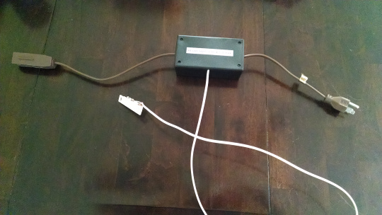
The circuit has to go in series with the air curtain's power cable. I decided to cut apart a three-conductor extension cord, and put the circuit into a plastic project box with the plug end of the extension cord sticking out one side, and the socket end sticking out the other side. That way I don't have to cut into the air curtain's power cable.
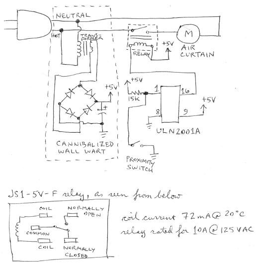
Most relays use a low DC voltage for the coil, so the circuit needs a DC power supply. The easiest option was to cannibalize a "wall wart". I had a relay on hand rated for 5 VDC across the coil, so I went looking for a 5 VDC wall wart at a second-hand store. I found one rated at 4.6 VDC (close enough to 5 VDC) for $1.50. I carefully cut the case open with a Dremel tool and a cutting disk.
The relay coil draws 72 mA, which is still more than the 37 mA that the proximity switch can handle, so I needed some sort of transistor to switch the coil current. I could have used a Darlington pair transistor, along with a diode to handle the backwards voltage created when the relay coil's magnetic field collapses, but I had an integrated circuit designed for that exact job on hand, so that's what I used. The ULN2001A can control as many as seven relays; I left the unneeded pins disconnected. I used a pull-up resistor to connect the proximity switch to the input pin of the IC, so that the voltage on that pin never floats; instead the voltage is either 0 or 5 VDC.
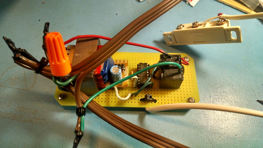
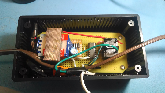
With the design finalized, all that was left was to build the circuit and put it in the box. I glued the guts of the power supply to the circuit board with epoxy. With the relay, I glued it to the circuit board with the pins facing up, and also strapped it to the board with a cable tie. I put the IC in a socket, just in case the IC needs replacement in the future. I mounted the circuit board on plastic standoffs for feet. When I was done with the soldering, I dabbed Liquid Electrical Tape (wonderful stuff) on my solder joints and other exposed conductors, and wrapped black electrical tape also where I could manage to. The circuit fit into the box snugly, so there was no need to permanently attach the circuit board to the box.
The circuit worked the first time I plugged it in! Hurray!
WARNING: any project connected to mains power is inherently more dangerous than a project powered by a few alkaline batteries. If you get it wrong, you could burn your house down in the middle of the night! At a minimum you should have a complete understanding of the risks of a circuit connected to mains power, and you should know how to calculate how much current / voltage / power each component in the circuit, including the wires, can safely handle. If you are not so qualified, then either get help from someone who does or build a safer project instead.
(Pop quiz: why is it important that the relay switches the hot line to the load, rather than the neutral?)
I'm publishing this project so that qualified like-minded builders can get ideas for similar projects. This document is not intended to be instructions to be followed exactly, which is why I left many details out.
| Description | Part Number | Manufacturer | Supplier |
|---|---|---|---|
| magnetic proximity switch | 617545 | Jameco | |
| enclosure | 18914 | Jameco | |
| circuit board | 105129 | Jameco | |
| relay | JS1-5V-F | Panasonic | Mouser |
| integrated circuit | ULN2001A | STMicroelectronics | Mouser |