
Paula NX1P met Steve K7KO and me on a scouting trip to a mountaintop site for a contest in which we planned to operate Field-Day-style. She brought a remarkable three-band QRP antenna of of her own design with her; she strung it up, connected it to her Elecraft KX3, and was soon making contacts. Paula told us that the antenna is partially documented on her QRZ page. Steve suggested that we make a few for ourselves and friends. I thought that was a great idea, so we did. This web page documents what I learned by modeling, building, and using Paula's design.
The antenna is an off-center-fed dipole, similar to a Windom, fed with a 4:1 current balun at the feed point, which is part of the antenna. In its simplest configuration, the antenna is a half-wavelength long on 20m. What makes this design really clever is that another piece of wire can be attached to the longer "leg" with alligator clips to make the antenna a full-wave OCF dipole on 15m, and a third piece of wire can be similarly attached to the longer leg to make the antenna a full-wave OCF dipole on 17m. The length of the shorter leg is the same for all three bands. The antenna can be rigged horizontally, or as an inverted vee or as a sloper. It's fairly light, it offers good performance on three bands, and the SWR is usually less than 2:1 across the full width of all three bands no matter how the antenna is rigged, so for many radios the tuner can be left at home. In short, this design makes an excellent QRP field antenna.
Here's a diagram of the antenna in its three configurations. Dimensions are as specified by Paula.

For those who aren't aware of the theory of an off-center fed (OCF) dipole, I'll try and sum it up in one paragraph. Start by considering a regular half-wave dipole transmitting at its resonant frequency. As you travel along the antenna wires, the measured AC voltage and current will vary. On a half-wave dipole the current is highest in the middle and zero at the ends, but the voltage is lowest in the middle and highest at the ends. At any particular point, the impedance of the antenna, if it were fed there instead of in the middle, would be equal to the (complex) voltage divided by the (complex) current at that point. So the impedance of the dipole can change quite a bit depending on where it's loaded, which gives antenna designers like Paula some freedom to be clever. The radiation pattern of the antenna doesn't change when the feed point is moved. Because the legs of the dipole are uneven, OCF dipoles can be a difficult challenge for the balun. If the balun isn't good enough, significant RF currents can flow on the outside of the coax shield, which can lead to RF in the shack, RFI, and other problems. Luckily for us, it's not hard to build a good balun for an OCF dipole at QRP power levels.
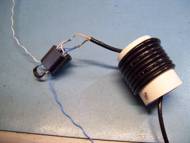
The balun is a 4:1 Guanella current balun designed by WVOH, which gets stuffed inside an eight-turn coax choke wrapped around a piece of 1" (2.5 cm) diameter PVC pipe. Just in case you're not clear about how to build the balun, here's a picture. Wind the coax around the 1" (2.5 cm) PVC pipe, with about 3" (8 cm) sticking out. Strip the outer jacket from 1/2" (13 mm) of the coax. Comb out the coax braid, twist the strands together, and tin them with solder. Remove the insulation from about 1/4" (7 mm) of the center conductor, and tin it.
Cut a 20" (50 cm) piece of ethernet cable. Pull out one of the twisted pairs, leaving its wires twisted together; I used the blue and white pair. Cut two pieces of the twisted pair about 10" (25 cm) long, still leaving the wires twisted together.
Glue the binocular-core ferrites together with a drop of super glue, and wind a twisted pair piece through the left hole of the bottom ferrite, looping up through the left hole of the top ferrite, and looping back down through the left hole of the bottom ferrite again. Make one more loop; the wire should go through the bottom ferrite three times and the top ferrite twice. Then do the same with the other twisted pair and the right holes of the ferrites. On one end, which will be the input, solder the two white wires together, and then solder them to the center conductor of the coax. Solder the two blue wires together and solder them to the coax braid. On the output side, solder the white wire from one pair to the blue wire of the other pair. The remaining white and blue wires will be soldered to the antenna wires. Insulate the soldered connections, and then stuff the balun inside the PVC pipe.
At first I tried to use heat-shrink tubing to insulate the soldered connections, but that was difficult and not practical. I found a much easier solution: Liquid Electrical Tape, made by Gardner Bender, available where electrical parts and tools are sold. It costs more than I had expected, but it's much easier to use than shrink-wrap tubing for this application.
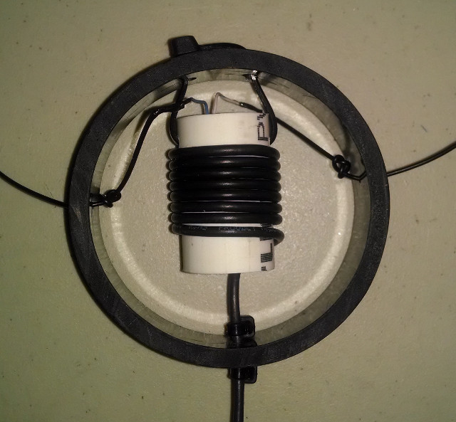
The center insulator is made from a slice of a 3" diameter black ABS drain pipe. You'll want to do something to keep the balun from flopping around. I drilled holes in the center insulator ring and also the PVC balun pipe, and then used a zip tie to attach the two together. I ran the coax through a hole in the center insulator ring, and put a zip tie around the coax on each side of the center insulator ring to keep the coax from slipping. I ran the antenna wires through small holes in the center insulator ring, and tied a figure-eight knot in each wire to keep the wire from slipping. It's best to put all the other parts inside the center insulator together before soldering the antenna wires to the balun.
So Steve and I built a couple copies of Paula's antenna using her published dimensions, but the SWR was too high and the frequency was too low. Whenever I homebrew an antenna, somehow I think that this antenna will work perfectly the first time, but of course that never happens. Homebrewed antennas need careful trimming to work right.
You'll need to raise and lower the antenna several times when trimming the antenna, so pick a place where the antenna is high enough and easy to raise and lower. Hopefully you cut the wires a bit longer than Paula's dimensions, in case your wires need to be longer.
Your first task is to trim the long and short wires for the 20m band. Disconnect the 15m and 17m wire links, raise the antenna, and find the frequency on or near the 20m band where the SWR is lowest. You'll want to trim the antenna until the minimum SWR frequency is close to the middle of the band, which is 14.175 MHz in the US. By the way, modeling shows that the minimum SWR frequency can move a few hundred kilohertz as the height of the antenna changes, so raise the antenna to the height you expect to use most often when you trim the wires. Trimming the antenna will make the minimum SWR frequency rise. The tricky part about trimming the antenna for 20m is that you'll need to trim both wires at the same time. You'll want to keep the lengths of both wires proportional to Paula's dimensions; for 20m, the long wire should be 3.69 times longer than the short wire. Measure each wire from the middle of the center insulator. Carefully trim the wires until the minimum SWR is close to the center of the 20m band.
Once the antenna is trimmed for 20m, the job gets easier because you'll only trim one wire for 15m and 17m. Next, attach the wire link for the 15m band, and trim the link to move the minimum SWR frequency on 15m to the middle of the band. Next, add the 17m link and trim that wire similarly to tune the antenna for 17m. Then you're done!
I always like to have a computerized model of antennas that I homebrew. Models generally predict the performance of an antenna very well, and it's easy to see the strong points and weak points of a design at a glance with a computerized model. In this case the model ignores the power losses in the balun and the coax, but coax losses can be easily estimated using an online calculator, such as this one.
Paula didn't publish her models for her design, so I had to create my own, one model for each of the three bands. (Download my 4nec2 models here.) My first computer models had satisfyingly-low SWRs on all three bands, but the frequencies were off. That's right, even my computer models needed tweaking. I shrank all the wires slightly to get the models to work properly.
Paula didn't say whether she modeled the antenna rigged horizontally, as a sloper, or as an inverted vee. In her QRZ page she does talk about attaching it to a 10m carbon-fiber fishing pole, which implies that she often uses the antenna as an inverted vee. So I decided to model the antenna both rigged horizontally like a traditional dipole, and also as an inverted vee with the ends drooping 30° down from the horizontal plane.
Here are the SWR graphs from the computer model.
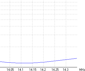
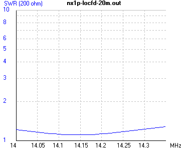
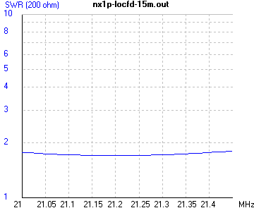
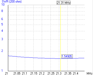
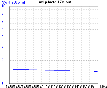
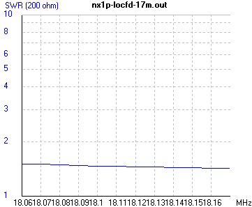
As you can see, the SWR curves are very broad: the SWR is low across all three bands. Also the SWR curves don't change much as whether the antenna is rigged horizontally or as in inverted-vee. This is excellent news for QRPers, because many portable QRP antennas are finicky: an antenna that was tuned for low SWR in the back yard often has a higher SWR in the field, so many QRPers are resigned to always bringing antenna tuners along with their portable antennas. Maybe the antenna tuner can finally be left at home when using this antenna!
Here are the far-field patterns from the computer model.
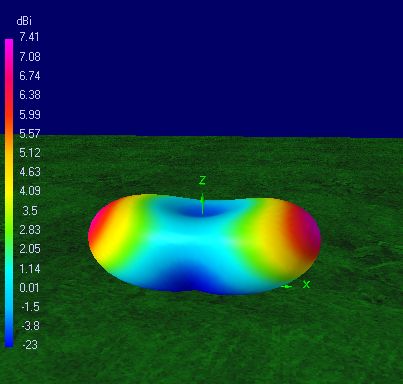
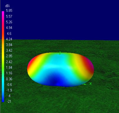
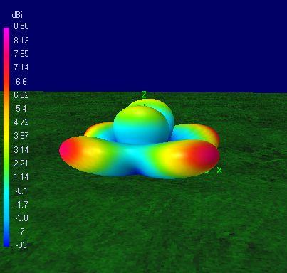
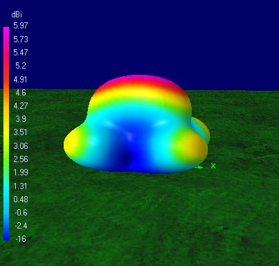
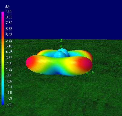
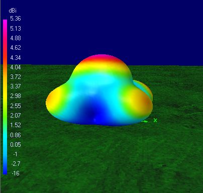
The 20m pattern looks as I would expect for a half-wavelength dipole, like a jelly bean, with broadside gain. The horizontal butterfly shape of the 15m and 17m patterns are typical of horizontal antennas a full wavelength long.
As I've seen before in modeling other antennas, drooping the ends of a horizontal dipole to turn it into an inverted-vee reduces the gain at low and medium takeoff angles, and promotes a lobe pointing straight up, which in my opinion has very little practical use on 20m through 15m. The lesson is clear: for these bands, the convenience of an inverted-vee generally costs several decibels of gain.
I was curious how much power a NX1P Linked OCF Dipole could take. The balun's designer, Myron WV0H, estimates that the balun could "easily" handle 20 W, or 100 W "at most". Steve and I used RG-174 for our copies of the antenna. I couldn't find a power rating for RG-174, but LMR 100A is similar, and I saw a power rating of 230 W for LMR 100A. So I would think that the balun would fail because of too much power before the coax. So let's take Myron's word for it and say that the antenna can safely handle 20 W.